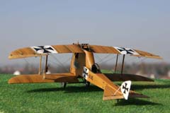
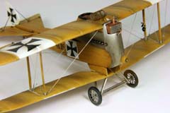
Planet Model's 1/72nd full resin
During browsing through piles of kits on 2007 GMM, something caught my eye. On
the first glance, I thought it's a spoof, or one of the goofy cartoon revivals when
Disney meets Batman. Then - no, this was real, a prototype of an imperial Austro-
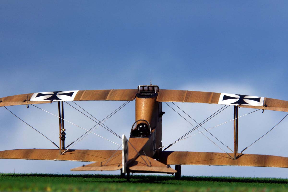
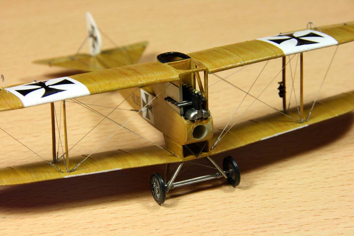
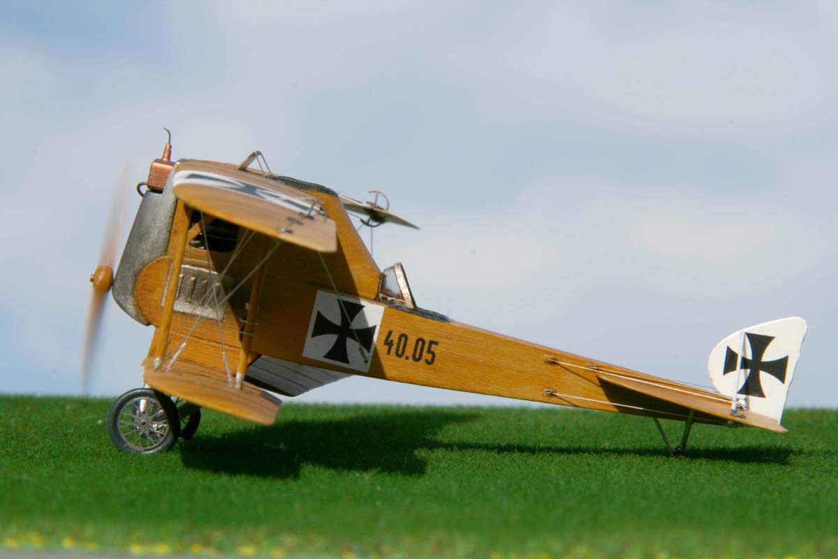
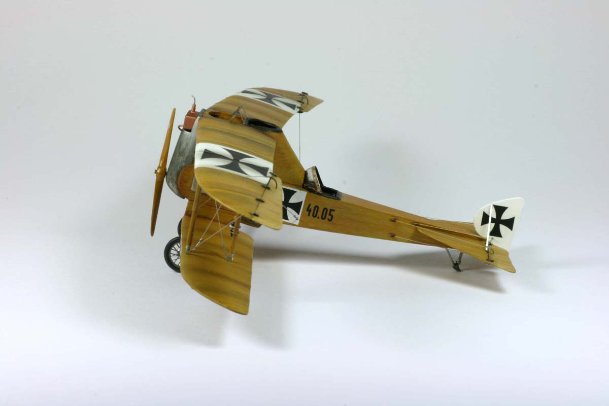
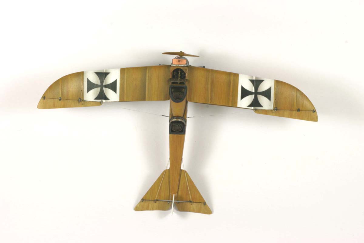
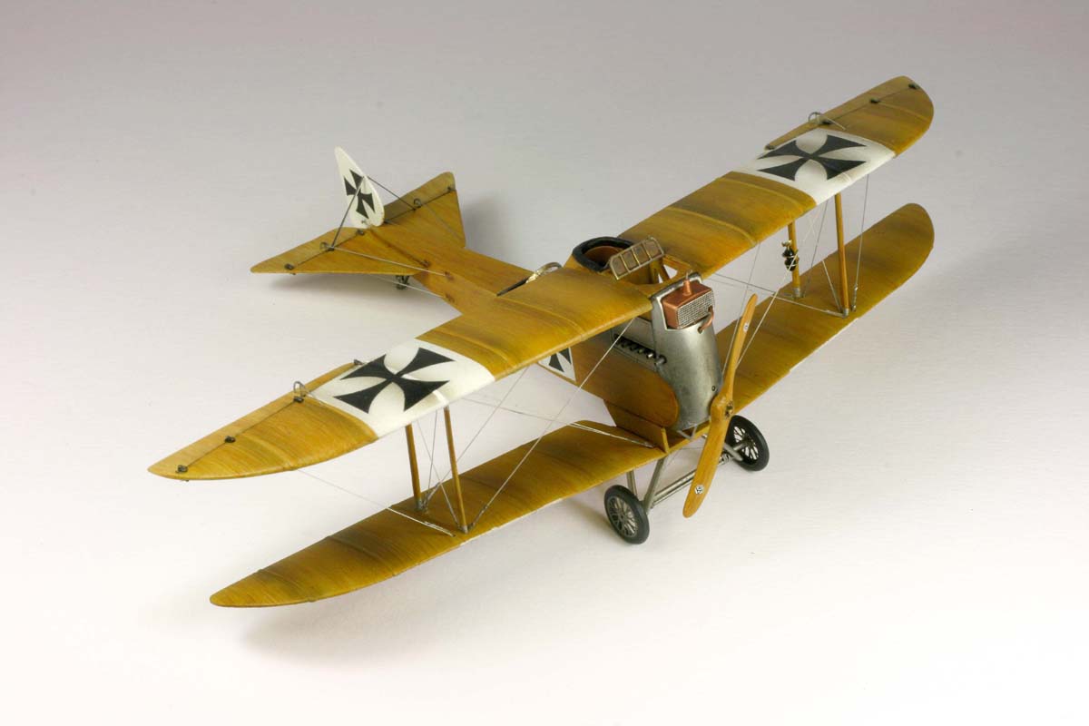
Hungarian (K.u.K.) biplane, the Lloyd FJ 40.05 Versce (Kestrel).
- I had to have it!
History:
The odd shape did have an explanation too: before synchronized guns shooting
through the prop were invented, many concepts were investigated in order to solve
this problem.
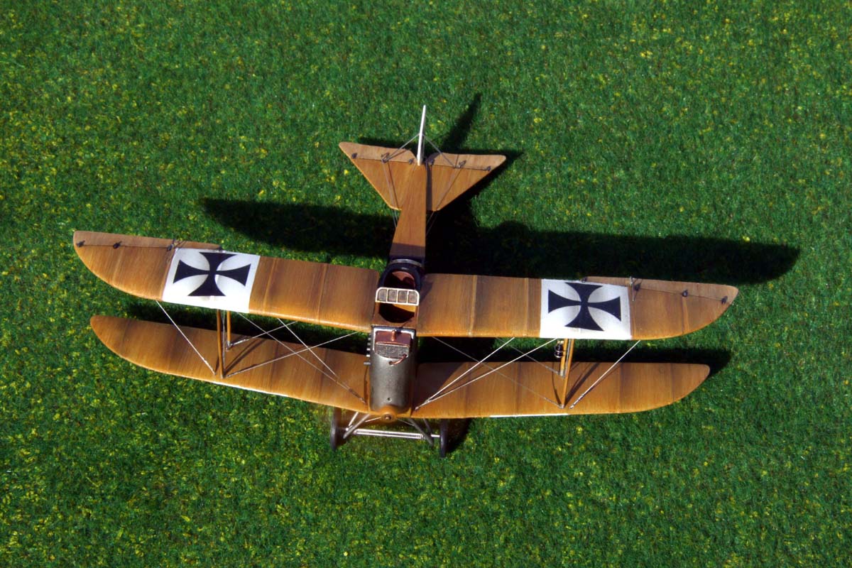
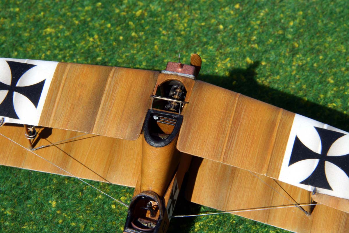
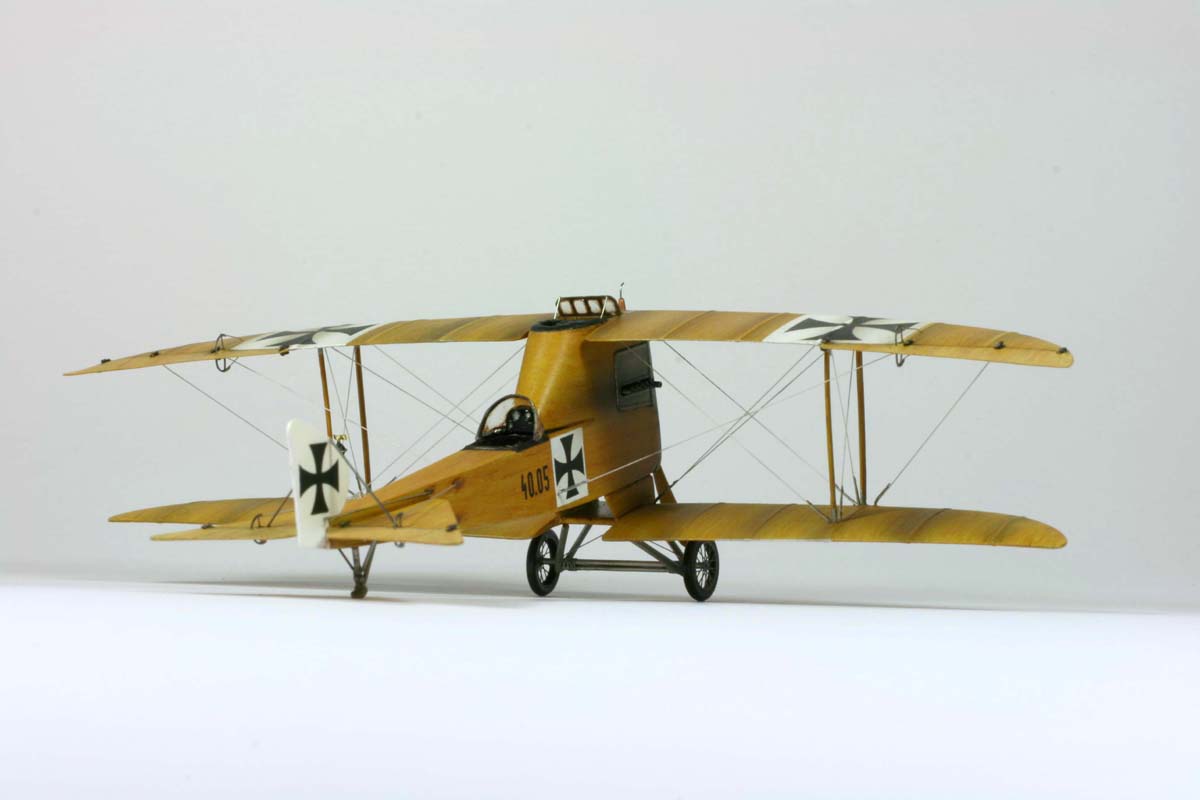
One of them was to have a gunner post, and shooting above the propeller area. This
provides for an excellent field of fire. Mind you, this concept worked nicely for many
bombers. Unfortunately, the 1915 Lloyd FJ 40.05 design proved to significantly
restrict the pilot's field of view. While this did not bother Lindbergh, and was no show-
stopper in crossing the Atlantic, it led to a quick demise of the FJ40.05. In January
1916 some flight testing was performed with the prototype, which reconfirmed the
concerns. Yet even a modified single - seater version of the plane with a pod
mounted machine guns didn't attract the K.u.K. Air-force's attention, so no mass
production was ever commenced.
The Lloyd FJ 40.05 was build to a then new process with a monocoque-like style.
The technique was patented by the inventor eng. Melczer, who was the technical
director of Budapest's technical university. In this concept, the skin consisted of thin
wooden veneer, rather than the so far common ribs and canvass. The effect was an
increased strength and actually a reduced weight of the structure, since the shell was
partially load-carrying, too. The “FJ” actually stands for ”Fournier- Jaeger” (=veneer
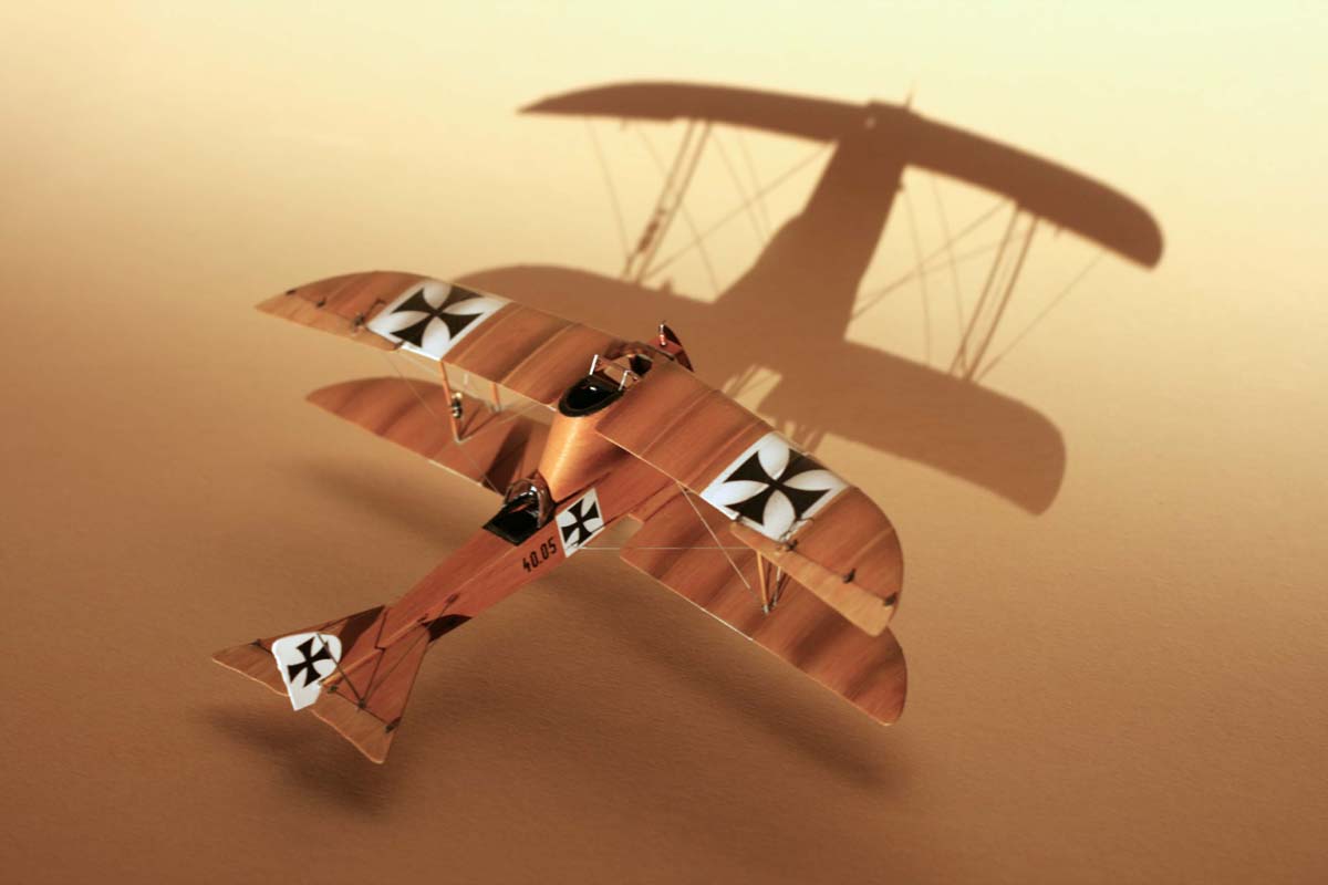
fighter). The disadvantage of this design was a strange and eerie noise which came
up when the structure was stressed, and the wooden elements rubbed against each
other. It awarded the aircraft the nickname “cock-a-doodle-doo” fighter. (I personally
prefer to call it the winged piano).
|
|
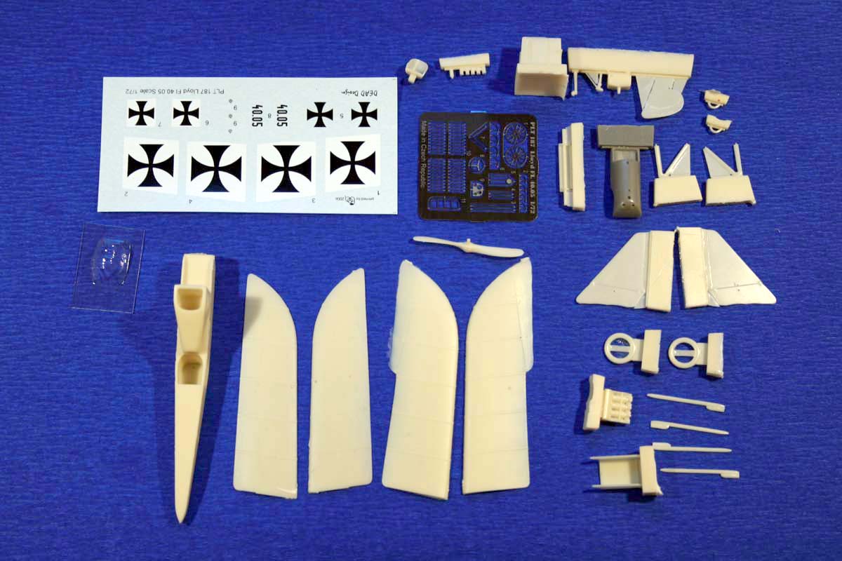
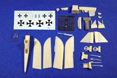
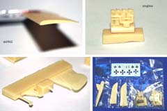
The kit
A multi-media kit, consisting of some 30 resin parts cast in ivory-colored plastic
(except for the gray engine cover), a small PE-fret, two vacu-formed canopies (yes,
one spare!) and a sheet of decals. All come packed neatly in their own
compartments of the plastic bag. The model is supposed to have a wingspan of some
16cm (6.5")
The description is in Czech and English. There are no text instructions, everything is
explained based on photographs of an partially assembled kit. The working steps are
not called out sequentially, so even though the plane's simple, you better know what
you're doing. The complex rigging is not sufficiently explained on the instruction, so
additional source of information (or at least the box top) are required.
The parts look well designed, with a nicely shaped airfoil-profiles of the wings. The
Daimler engine and the cooler have good detail, but they look a little washed out -
maybe the molds start showing some wear. Still, with some wire and some sanding
the parts can be brought to the desired condition. The parts show no bubbles, of
other casting defects what so ever, the trailing edges are razor-thin. If I could wish for
something, then maybe for some faint wood grain. On the other hand - in this scale,
maybe not.
While not cheap (I paid 27 Euro at Premodels - and that's practically directly from
Czech republic). I think it's worth it, just for the sake of it's originality.
|
|
Construction
My love for the exotic - this little kit managed to work itself up the way on my priority
list, and there it goes, finished at last, after some six months.
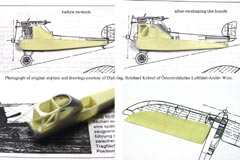
Research
The work started - as so often - with a web search session. No much there, yet
actually a link to the Austrian Aviation Archive
(Österreichisches Luftfahrtarchiv).
After contacting this organization, I was kindly provided with a publication containing
a description, plans and a photograph. In this context I’d like to express my thanks to
Eng. Reinhard Keimel for provided support, which inspired me to carry on.
The first step was comparing the resin chunks to what is seen on the plans and
pictures. On the first glance the biggest difference was a mismatch of the large hunch
(which contained the gunner’s post) to the plans. The position and angle were quite
far off. Another bit was that the part of the fuselage above the engine, and between
the wings was made solid in the kit, but looked open on the picture and in the plan. A
comparison of the wings also showed a deviation.
|
|
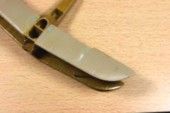
Plastic Surgery
Since I had more trust in the plans than in the kit, I started re-shaping the parts. What
looked like a minor facelift at the beginning, ended as a major plastic surgery in the
end:
The hunch was not only wrong in the angle - it was also off in the position. The
geometry was partially re-built using several layers of Mr. Surfacer 1000 to create the
additional volume. Even though this liquid putty had to be applied in many layers, it’s
stronger than usual putties when dry, and the adhesion is better (on resin), too.
The resulting wall partially consisted of the base material, and partially of Mr.
Surfacer. On top of that, it was undercut and thinned to a reasonable thickness, so a
strong bond between old and new material was mandatory. I corrected the angle, but
did not re-set the hunch itself, accepting a small difference to the plan - it looked
good enough to me. The fuselage was hollowed-out around the pilot’s and gunner’s
cockpits with a ball-tip milling cutter, and some structure details added with bits of
tape.
The engine compartment roof was removed and replaced with a small bridge, which
was reinforced with metal pins. The shape of the wings was also somewhat off, but to
my eye, still to an acceptable degree. A re-shaping here would mean also adding
material in tricky areas, with little visible effect, so I’ve just let it be.
|
|
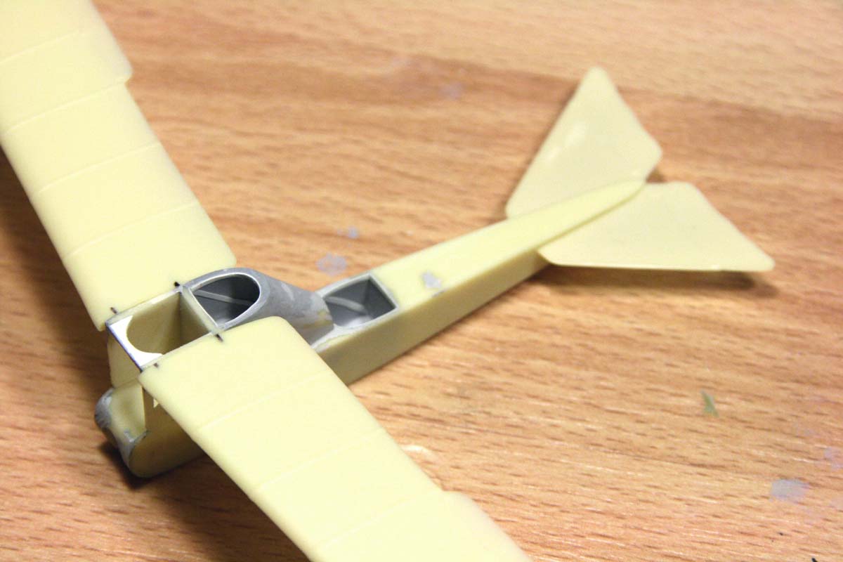
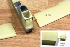
Starting the assembly
The first step was to install the walls of the engine “cage” on the fuselage, and then
the top wing. For this purpose the wings and the walls received small holes, and
therein metal pins installed. Tricky part was not to collide with other pins, which were
holding the bridge between the walls in place, and at the same time prevent the drill
from drifting off, and coming out on the outside of the thin wall. A deep hole was
drilled into the front end of the massive resin hull, to later contain the rotor bearing.
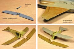
The bottom wing was attached also with metal pins to a box which was supposed to
position the lower wing closer to the ground, and further away from the fuselage. The
tail assembly was simple, with no complications. At this time, it was time for first
painting.
|

|
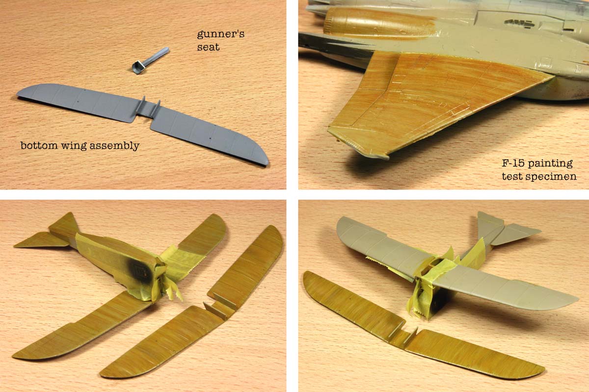
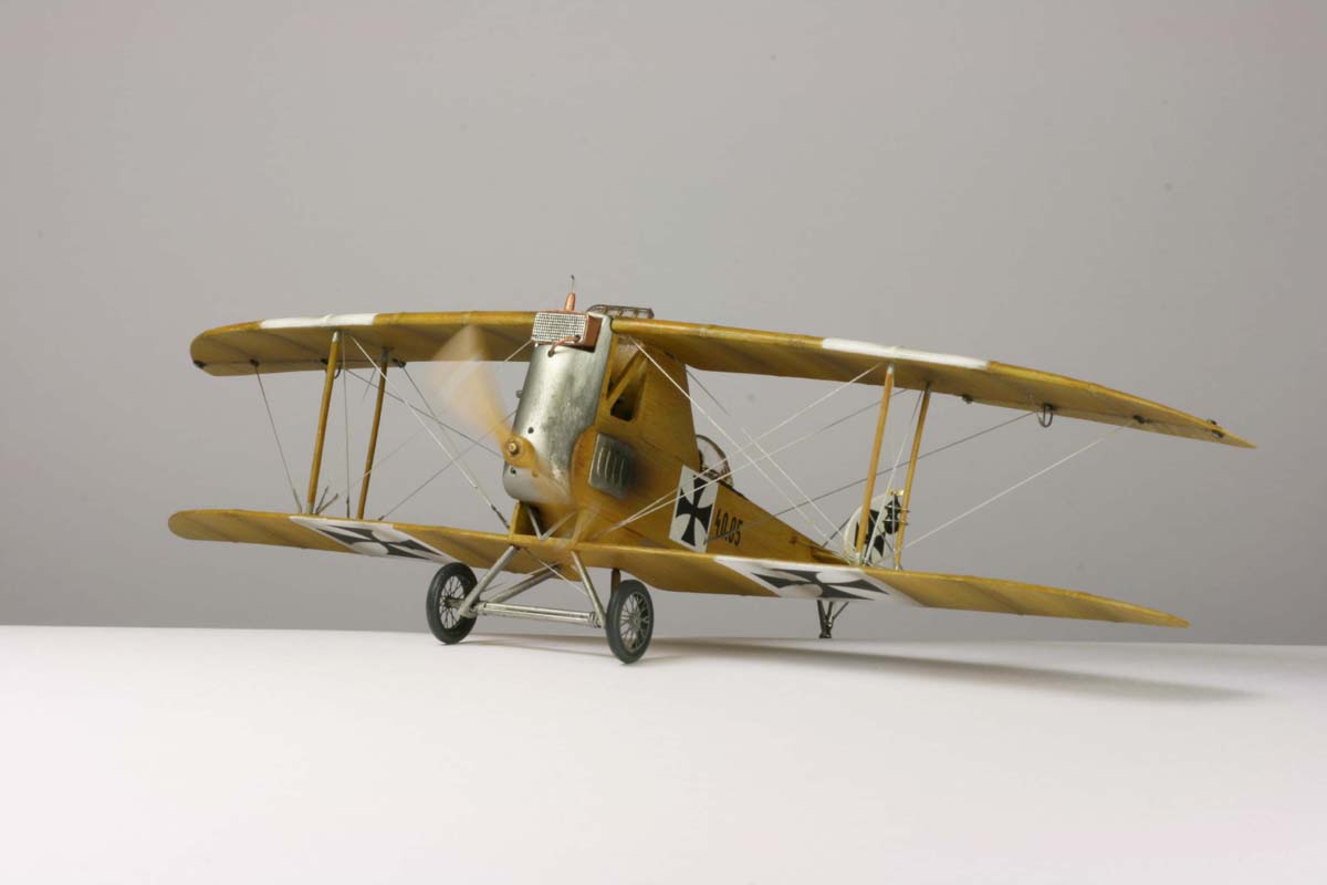
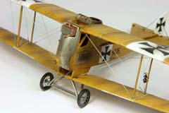
Painting
In order to prevent having to paint between the wings, when the tensioning cables
were applied, I had to paint the space between the wings first. To get into this space
without bigger problem, I attached only the top wing in the initial step. At the outset,
the area between to be painted received a Mr. Surfacer priming, and then a coat of
Tamiya buff XF-57. Then the wood pattern had to be applied: the process was
beforehand experimentally tested on my old trusty F-15. After having the cabin-look
perfect on the jet's wing, on it went to the biplane. I used Schmincke Mussini artists
oils thinned only a little, put on with a rough bristle brush, wet in wet. After a little
drying, the wood grain was streaked with the help of a tooth-brush. The main color
was raw Sienna. To make it livelier I added streaks of light raw umber, natural burnt
Sienna and attish light ochre.
In the first painting step, the projected bottom side of the assembly so far was
colored, and the upper side of the lower wings. The coating took about two weeks to
dry through, which slowed down the building progress considerably, because all in
all, I had to repeat this process four times for different areas. The aluminum parts
received a quick black priming, then an Alclad coat, and after the attachment of the
lower wing assembly to the fuselage, the bird was ready for rigging!
|
|
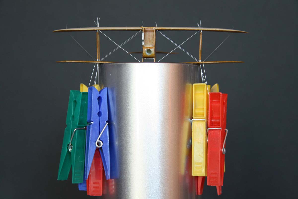
Rigging
The rigging was a little complex, and only with the instruction really hard to apply.
Looking at the plans and picture at the same time allowed me to get an impression as
how the cables are supposed to run. I drilled the wings through with a short 0,25mm
drill, top and bottom, and fed thin nylon mono-filament through the whole contraption.
The fibers were attached on the top with superglue. At this point the somewhat
softish wing struts were added. On the bottom of each thread I clipped on cloth pins,
and let them hang overnight. That way the threads adapted to the sharp deflection
angles.
The pins were removed, the plane turned upside-down, and tensioning each
thread with one hand, I fixed it with superglue. The holes were then filled up with
Surfacer, and sanded flat. The rest of the wooden pattern was then painted on.
I decided that the rudders and ailerons should be made of different wood, so I mixed
the artists oils with some white, to get a brighter shade.
|

|
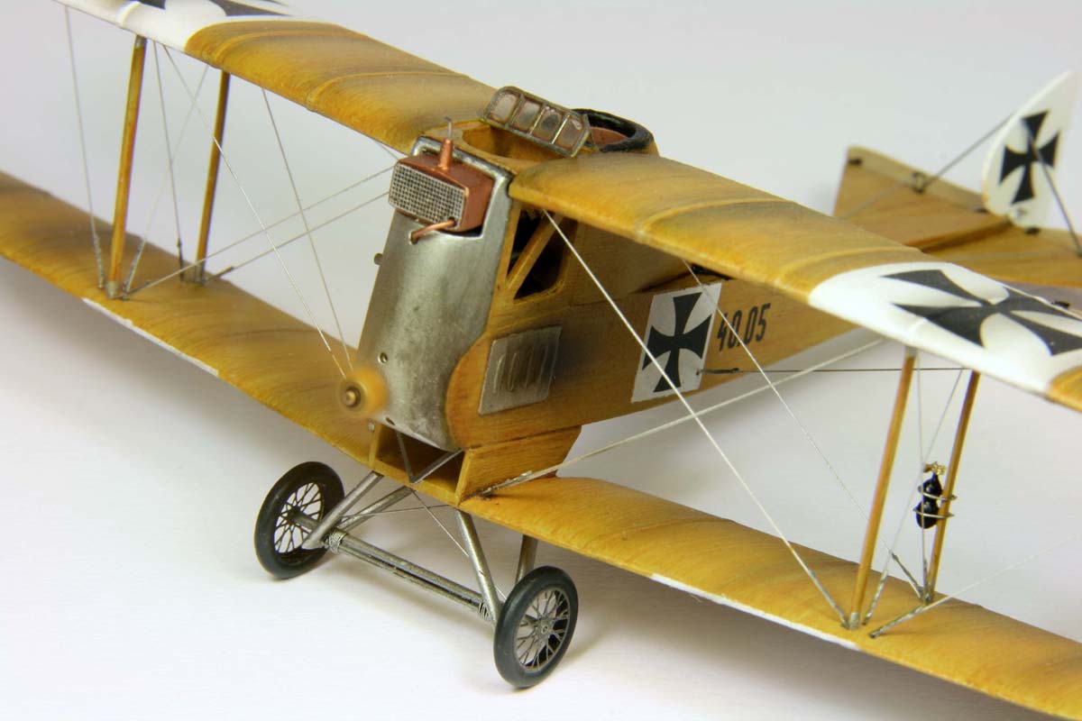
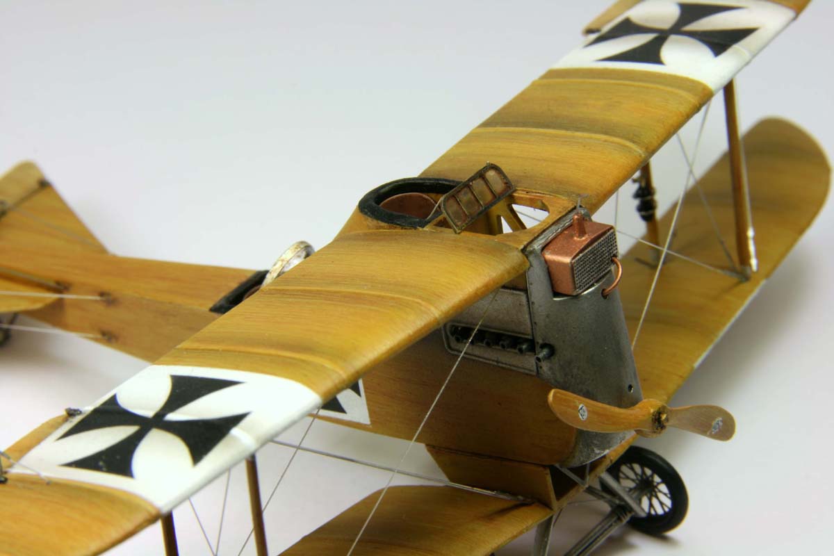
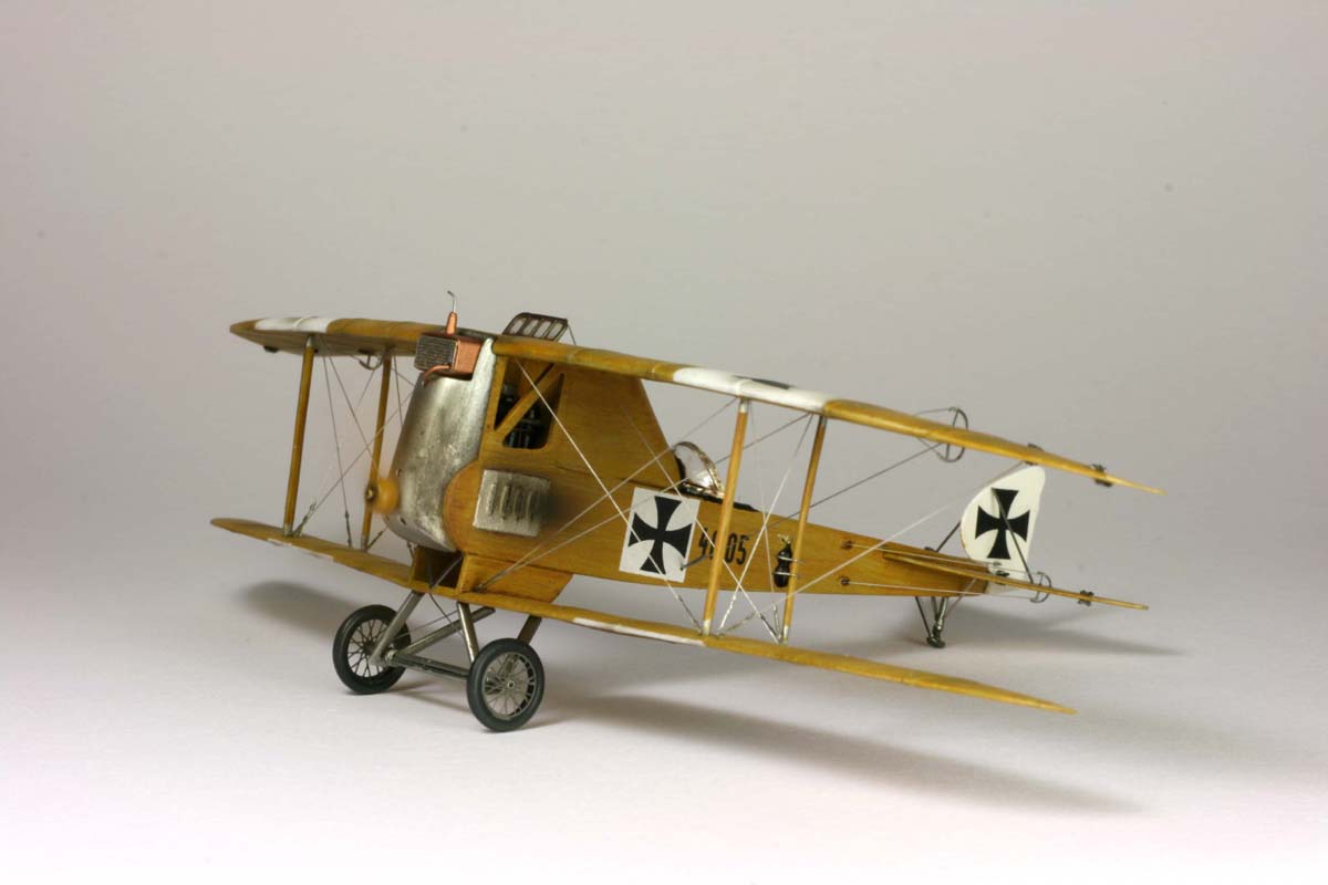
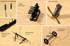
Engine cowling assembly
The cowling was a big chunk of gray resin. For photographic reasons, the prop has to
rotate, so I attached a tube to the back of the cowling as a the prop shaft bearing,
and a pin to the prop, so it would run smoothly, when assembled. In order to make
the engine fit, I had to mill-out nearly all of the material on the back, to form only a
thin shell. Then the cowling got a coat of Alclad. The cooler was painted with Revell
copper (92) and Alclad, equipped with a syringe needle, and glued on the cowling. A
piece of thick syringe was added as the first exhaust pipe, and the prop installed.
Engine assembly
Initially I wanted to keep the original resin engine, but decided, that is has too much
visibility to have half-cylinders front and rear. So I scratch-built a new one. Chunks of
2mm brass tubing made the Daimler's six cylinders, pieces of wire sticking out on top
the valve shafts. Crank case was made from pieces of a 72nd scale bomb from the
scrap box. The cam shaft was made out of a simple pin, and the rockers symbolized
by bent pieces of brass sheet. Exhaust tubes were cut from 0,8mm syringe, and the
intake manifold was done from soft wire, covered in Surfacer 500. Cooling lines from
hair-thin copper wire, and there goes my engine! Painting was fixed by Tamiya black,
Alclad and Humbrol metal (53).
|
|
Landing gear assembly
The tires got a paint of Tamiya black, the spokes of the wheels came from the PE
fret. The provided bits of the axle were quite gross, so I decided to make my own. A
piece of syringe served as the hollow axle, two pins as spacers, and a several
windings of nylon filament to bind them in place. The loose ends were used as
tensioning lines for the landing gear assembly. The alignment of the subassembly
was quite tricky, in particular the V-struts. I used calipers and tape to get the positions
of the parts right, but after some superglue, it didn't look bad at all.
Bits and pieces
I glued small bits of PE on the tensioning strings, which are supposed to pass for pre-
loading devices. A generator was made of bits of plastic, and a piece of brass sheet.
The plastic for the generator body was coated with Surfacer to form an 8-shape , the
brass cut to roughly resemble a small prop, and then its blades twisted. It was
painted black, the tiny rotor glued on top, the part then attached to the strut with two
thin coils of wire. The levers of the rudders made from folded bits of sheet were
added, as well as control cables for the rudders. I added hinges to the rudders and
ailerons, and the skid below the rear end.
|
|
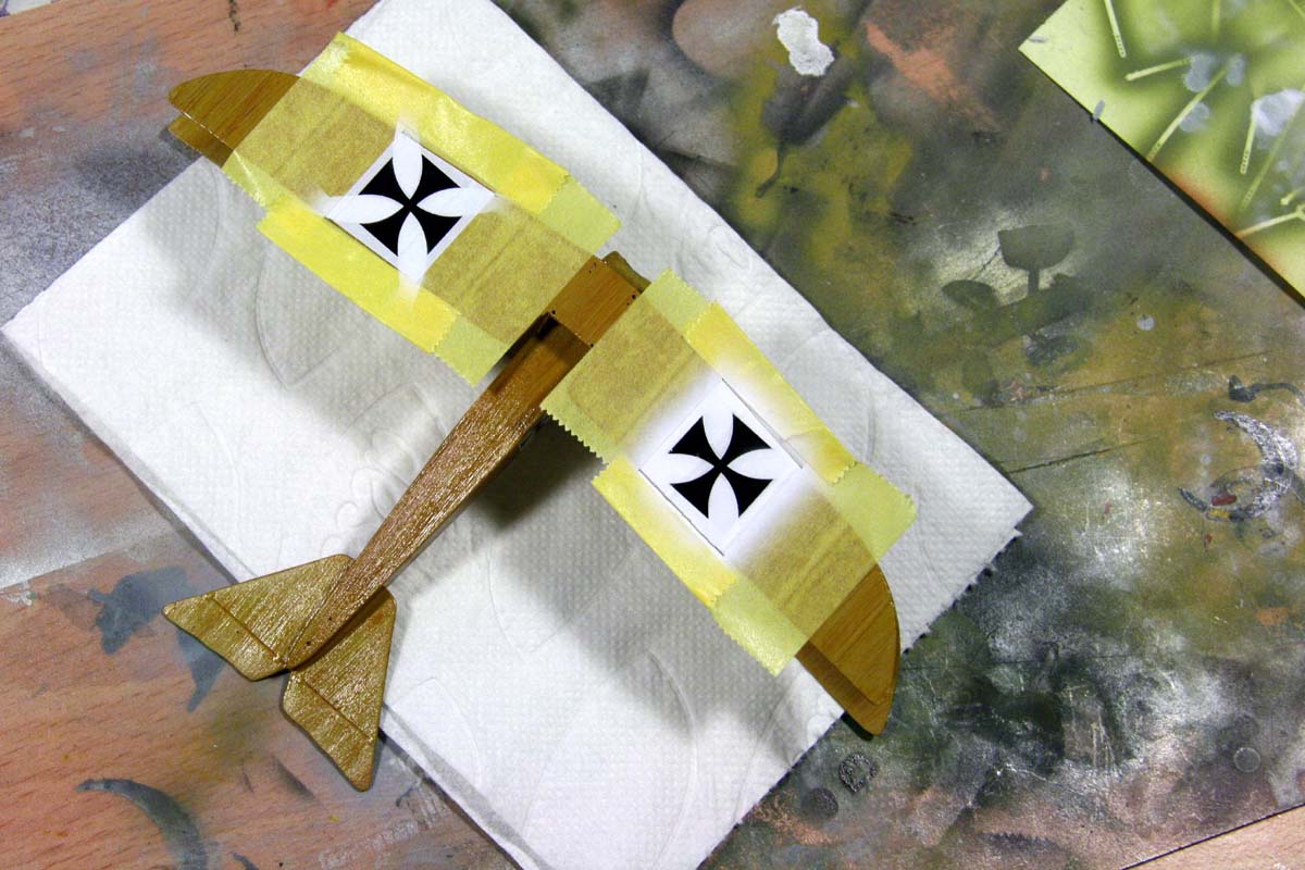
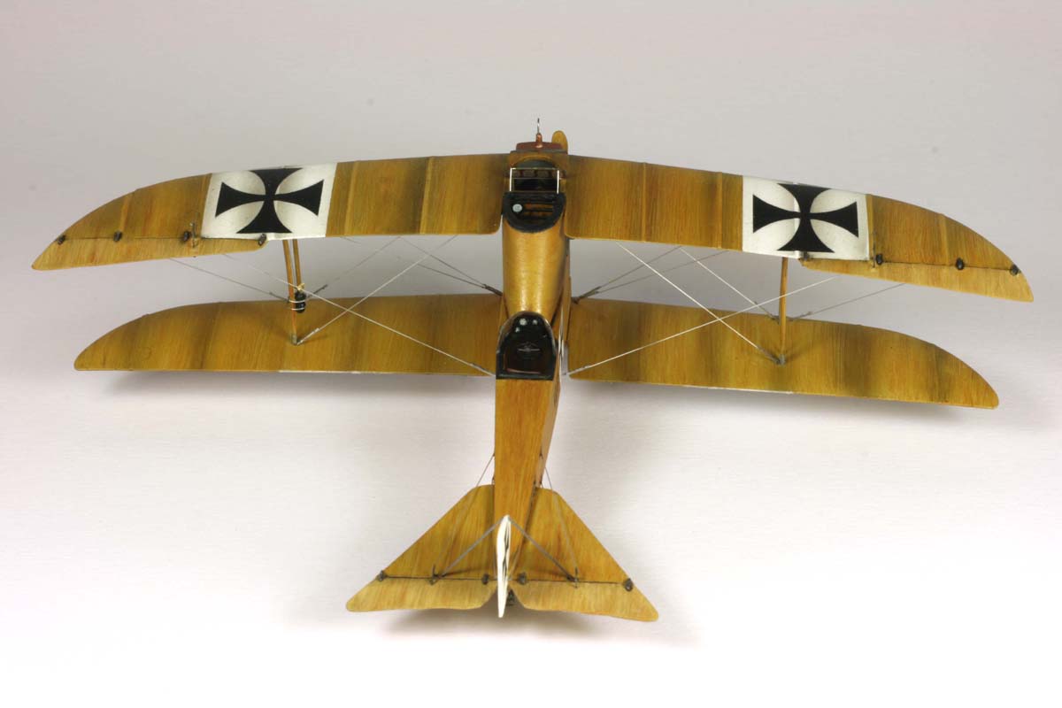
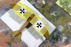
Decals
At first I applied a coat of future, in the areas where decals were supposed to go. The
kit's decals by "Dead Design" were already hinting at what was coming up: While
rather thin, they were completely impervious to any softener, and started cracking on
the edges. On top, they were somewhat transparent, and the wood grain showed
through. I sanded the fractures out, and prepared simple masks from post-it notes, to
spray white around the black crosses. The decals on the fuselage were put on with a
lot of care, and went OK. On the upside, the decals did not silver.
|
|
Cockpits
For the gunner's cockpit I had to scratch-build a new seat, which was then equipped
with simple hip safety belt from a small PE fret I've found in the bits-and-pieces box.
The instruments came in the kits. The seat for the pilot was in the kit (again PE belts
added), as well as the steering column. The steering wheel and the instrument panel
came also from the PE-set. The panel was underlain with a clear foil, which was
painted white on the rear side. I scratched in the scales and needles of the
instruments, and then painted also the back side black. The borders of the cockpit
sides were padded up with Surfacer 500. The masking in this area was tricky, so I
took pieces of old decal, and applied them on the padding with a lot of softener - to a
nice effect.
Windshields
The gunner's wind shield was also part of the kit's PE offering. Glued on a piece of
clear foil, I cut it out, glued on the plane. The pilot's canopy was provided in the kit, as
a vacu-formed part. I cut it out with small scissors, and superglued it in front of the
pilot’s carrel. The frame was fixed from a strip of thin aluminum foil.
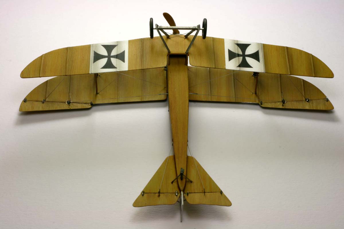
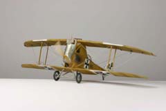
Finishing
The engine was set into the fuselage, and the cowling glued on.
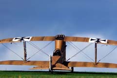
Weathering
Pre-shading was not an option with the used technique, so I tried something different:
thin coat of Tamiya smoke was applied to give the wing some plasticity. On top I
masked the ribs, and sprayed only on their outside. This generates the impression of
additional depth. Between the wings, where I could not really mask, I applied this
shading free hand, with acceptable effects. The smoke traces from the exhausts
were sprayed on behind the pipes and behind the crank case venting. Some traces
inside the cockpits, on the landing gear and in joints were accentuated with thinned
black and burnt umber artist oils. The cowling had initially an accident: I tried to clean
some fluff from the surface with alcohol, during which the paint was stained. I thought
about re-painting it, but then decided that it's convincing enough as old metal. The
tires were brightened up with some pastels. Initially I wanted to keep the plane
glossy, but then decided to give it at least partially a flat finish. In the end, I applied
different gradients of "flatness" in different areas, to achieve the optimal effect.
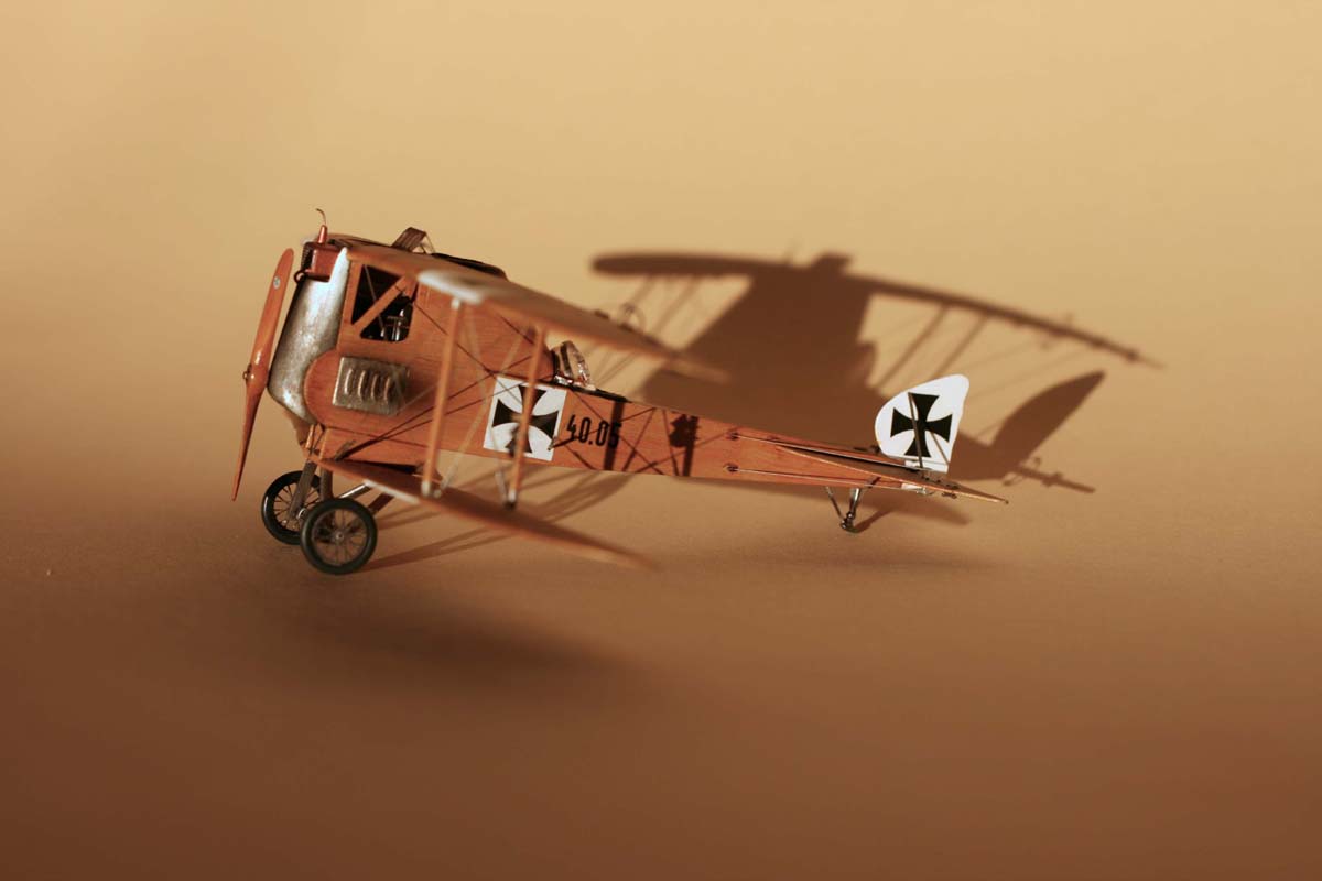
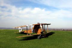
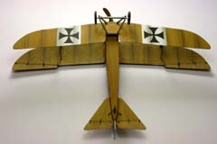
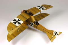
Conclusion
The little winged piano asked for a lot of work, but resulted in a real eye-catcher.
While I'm not too deep into WWI material, this little biplane was fun to build, and is
even more fun to behold.
|


|
literature:
FLUG-Informationen IV/1991 WIEN
(publication of the Austrian Aviation Archive)
all photographs copyright J.Kierat
except photograph of original aircraft and plans which are copyright of Austrian Aviation Archive.
no use without authors permission
|